

 en
en ru
ru es
es ar
ar


V&T Inverter For Mine Shaft Hoist Transformation Project
Ⅰ. Shortcomings of traditional mine shaft hoist
Conventional mine shaft hoist generally uses concatenation resistance of rotor loop, which adopts the disconnection and close of the contactor to achieve step-by-step speed regulation of the motor. This method has the following obvious disadvantages:
◆ The speed regulation of concatenation resistance belongs to the pole speed regulation, the starting impact was large, and there was a speed jump in the speed switching. It was easy to drop, and the more dangerous, which seriously affects the production efficiency and the safety of people's lives and property, especially when the transporting passengers.
◆ Using concatenation resistance to regulate speed, the serious waste of energy on the resistance, the lower speed, the more serious waste. when the object was lowered, the motor was in the power generation state and It wastes energy more seriously.
◆ Rotor concatenation resistance for speed control, high failure rate, many maintenance workload. Due to the contactor for speed regulation of concatenation resistance, frequent switching during speed regulation causes the contactor damaged frequently, resulting in malfunction of speed regulation. there was a safety hazard and Increased maintenance workload.
◆ Poor stability and speed change with load.
◆ The starting torque was not enough, especially when it stops in the slope and can't be restarted. It was necessary to put the material down to a stable place and start again, which seriously affects the production efficiency.
Ⅱ. V&T Inverter for mine shaft hoist Integrated control solution has obvious advantages in driving the motor:
◆ Adopt advanced DSP chip and excellent vector control to match the power required by the hoist and the output power of the inverter;
◆ The starting current was small, the starting speed was stable and no impact, which reduces the down-going phenomenon well;
◆ High reliability, the inverter has perfect protection functions, such as over-current and over-voltage overload and short circuit protection functions;
◆ Low maintenance workload. There was no need to replace the contactor frequently as in the conventional solution, which reduces maintenance costs;
◆ Wide range of speed regulation. It belongs to the step-less speed regulation, the motor control was stable during the acceleration and deceleration process, and the operation was smooth when speed was adjusted.
High system reliability, and there was no heat generated by the concatenation resistance, which improves the working environment of the operator.
◆ Large energy saving space. When the mine hoist was in the elevated state, the energy saved was proportional to the speed; when in the lower state, the motor was in the power generation state. If the energy feedback unit was used, the energy saved was not only proportional to the rotational speed, but also the energy fed back. ;
◆ Moreover, It has the automatic switching function of transporting people and things. When transporting people, It can automatically limit the maximum speed, making the transporter more safe and comfortable.
◆ It can be used perfectly with mechanical brakes and safety circuits. When using mechanical brakes, the inverter will not experience overload and over-current, and it can automatically realize mechanical brakes in case of emergency or power failure, maximizing the protection. Safety;
◆ Greatly improved production efficiency, high stability, and speed does not change with load changes;
◆ It can eliminate the hook phenomenon. Even if the mechanical brake was carried out in the middle of the ascending process, it was not necessary to put the heavy object on the flat ground to restart, and the heavy object can be pulled up without slipping in the middle;
◆ The raising and falling processes are interlocked, and it was not easy to cause operational errors;
◆ When running at high speed, it was not possible to change the running direction at will, to prevent the inverter from automatically stopping or reversing due to accidental signaling during operation.
◆ Do not change the original operating habits;
◆ Support power frequency and frequency conversion switching function;
◆The operation panel has a parameter copy function, which reduces the workload of Commissioning and maintenance well.
Ⅲ. About the brake and lock of the winch
◆ About the brake problem of the winch:
1.1. The “+” and “—” terminals of the brake unit are connected to the “+” and “—” terminals of the inverter.
1.2. Braking resistance terminal of braking unit was connected to braking resistance
Note: The load on the winch was heavy, and the selection of the brake unit and braking resistance should be large enough. Regarding the feedback device, the installation method refers to the instruction of the feedback unit. It was recommended to use the brake unit for a high cost performance.
◆ Brake problem of safety circuit:
The mine was a very safety-conscious place. It must be equipped with mechanical brakes. It must be ensured that the mechanical brake can completely brake and lock the vehicle under any abnormal conditions. For example, in case of emergency, when the inverter fails, suddenly power failure occurs. At the time, etc., it must be ensured that the mechanical brake can fully perform the brake;
When the inverter was in the stop state or the inverter has almost no speed, if It does not have the brake function, it needs mechanical braking;
The inverter has various protection functions, such as over-current, over-voltage, overload and under-voltage protection. When a fault occurs, the inverter stops outputting the motor immediately, so the brake protection was required at this time.
As can be seen from the above, the entire system must have the above security protection functions. Normal winches should have the above functions integrated into the safety loop of the winch. When there was a problem in the safety circuit, immediately start the mechanical brake and immediately output the switch signal to prohibit the inverter from running. The switch was connected to the X terminal of the inverter. The function setting was 22: The inverter operation was prohibited.
◆ Problems with manual mechanical brakes:
In the normal driving process, the brake and winch brakes are fitted with a contactor in the middle of the mechanical brake. When the brake was actuated, a signal was output to the inverter. At this moment function was set to 21: External interrupt contact Input, (if set to X4), it was best to output a signal to the drive when the brake was released for half (half tight).
If the current state was the stop state, then the brake of the winch was holding tightly. At this time, the inverter was started. At this time, the brake was slowly released. When the release was not up to half, the X4 terminal should be closed. Although the inverter runs, it was in the blocked output state, and the output frequency was zero. When it was released to half, the X4 terminal was set to the off state. At this time, the potentiometer was turned to a little speed, and the inverter starts running. When you hear the sound of the motor, It means that the torque of the inverter has been fully established, and then slowly release it. At this time, the potentiometer was rotated and the motor speed can rise slowly.
When the winch was in operation, prepare to brake the winch with mechanical brakes. At this time, you can slowly slow down slowly. When it reaches a certain level, slowly tighten the mechanical brake. When the mechanical brake was at halfway, the above setting was made. The function terminal No. 21 was closed. At this time, the inverter blocks the output, and the mechanical brake brakes the winch to stop.
Ⅳ. Pay attention to
◆ At present, the inverter was suitable for environment without gas and coal dust explosion, environment without significant vibration and impact, ambient humidity: ≤90%, waterless condensation, power supply voltage: AC380V 50Hz, If explosion protection was required, please choose V&T company explosion-proof series inverters.
◆ In mine production, It was necessary to ensure the availability of safe protection devices, such as checking whether the brake system was intact, whether the gap of the gate was normal, and whether the direction was interlocked;
◆ The electromagnetic mechanical safety brake was electrically interlocked with the inverter. After the electromagnet was energized, the inverter can be started. After the inverter fails, the safety brake was tight.
◆ The inverter forward/reverse switch was electrically interlocked with the manual brake. The inverter cannot receive the start signal until the manual brake was released.
◆ The electric lock of the manual brake was electrically interlocked with the speed-regulating potentiometer. When the potentiometer was adjusted to 0V for 5Hz operation, the manual brake was returned once, the inverter immediately outputs at zero speed, and the inverter was stopped at the same time.
◆ From the perspective of safety, the inverter power should be more than the rated power of the motor. For example, if the motor was 220kW, the selected inverter should be at least 280kW. In addition, a dynamic braking unit or a feedback braking unit was required. The coal mine was a very safe place, requiring mechanical brakes and safety circuits fully coordinated.
V. Renovation Case 1: Reconstruction of large winch in a city's leading coal mine (180kW)
◆ Wiring diagram of the main circuit and control circuit of the inverter (the wiring diagram of AI2 was not shown here):
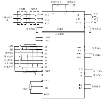
◆ Switching schematic diagram and switching method of power frequency and frequency conversion system :
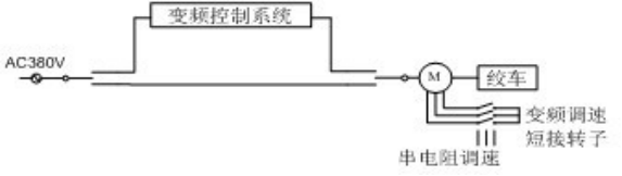
When using the inverter, please connect the power switch to the inverter input power R, S, T, and connect the motor wires U, V, W to the inverter motor output terminals U, V, W, and also need to shorten the rotor circuit of the motor.
When using the power frequency, the switching power supply was connected to the original operating system. In addition, the motor wires U, V, and W need to be connected to the power supply at power frequency . In addition, the rotor wire needs to be connected to the original concatenation resistance circuit.
◆ V&T Inverter Commissioning methods and steps:
1. Input parameters according to the motor nameplate:
P0.11: Maximum frequency, set according to site requirements;
P0.13: The upper frequency limit was set according to the site requirements. this value can be the same as the P0.11 setting.
P0.12: Maximum output voltage, please set according to the motor nameplate;
P0.15: Basic running frequency, please set according to the motor nameplate;
P9.00: Load type, please set 0, which means overload;
P9.01: Number of motor poles, please set according to motor nameplate;
P9.02: rated motor speed, please set according to the motor nameplate;
P9.03: Motor rated power, please set according to the motor nameplate;
P9.04: Motor rated current, please set according to the motor nameplate;
2. Set P9.15=1 to perform motor static self-tuning, and it will automatically stop after self-tuning.
3. Connect the potentiometer to between 10V, AI1 and GND, then set
P0.04=1: given frequency through AI1
P0.06=1: terminal control
P3.09=0, allow reverse
P6.00=4410, AI1 and AI2 are corrected by curve. When transporting people, switch potentiometer to limit speed.
P6.02=2,
P6.05=2,
P6.08=25;
4. Set the function of multi-function input terminal:
P5.00=2: X1=forward rotation
P5.01=3:X2=reverse
P5.02=20: X3=Fault reset
P5.03=21: X4= external interrupt contact input, connected to mechanical brake signal
P5.04=22, X5=prohibited inverter operation, connected to safety loop
P5.05=55, X6=human-car signal switching, connect a potentiometer at the AI2 end, and switch the frequency source when the transport needs to speed up;
P5.06=26, X7=fastest parking;
5. Set the multi-function output terminal:
P7.00=00: Y1=Inverter running signal
P7.01=15:Y2=inverter alarm signal
P7.02=14: Relay = inverter fault signal
6 connected to the analog output terminal:
P7.03=53: AO1=inverter output voltage
P7.04=50: AO2=inverter output current
Ⅵ. Transformation case 2: transformation of a medium-sized winch in a coal mine in a city (95kW, 55kW)
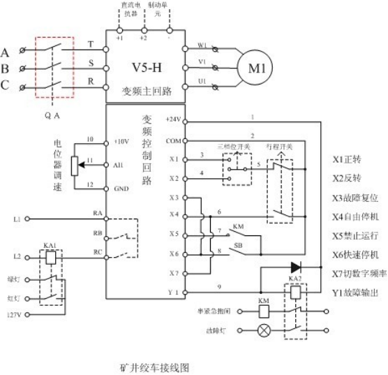
◆ The main circuit and control circuit wiring diagram of the inverter:
◆ Parameter setting:
1, motor parameter settings:
P9.01=****, the number of motor poles, please set according to the motor nameplate
P9.02=****, motor speed, please set according to motor nameplate
P9.03=***, motor power, please set according to motor nameplate
P9.04=***, motor rated current, please set according to motor nameplate
P9.15=1, press RUN key after pressing to perform parameter auto-tuning
2, function parameter settings:
P0.04=1, analog given frequency
P0.06=1, terminal control run command
P0.08=50, acceleration time (set according to actual situation)
P0.09=15, deceleration time (set according to actual conditions)
P2.00=3, keyboard lock function
P3.03=2, starting frequency
P3.04=0.5, starting frequency retention time
P3.09=0, allow reverse
P5.00=2, the terminal runs forward
P5.01=3, terminal reverse running
P5.02=20, fault reset input
P5.03=24, the terminal was free to stop
P5.04=22, the inverter was forbidden to run
P5.05=26, fast shutdown
P5.06=52, the main frequency source was cut to the number
P6.00=4440, analog correction
P6.02=5Hz, analog 0V corresponds to 5Hz
P7.00=14, output frequency conversion fault
P7.02=0, the signal was running in the inverter
P9.18=20, motor overload protection time
PA.09=1, energy brake has started
◆ On-site situation before the renovation:
The coal mine has two unidirectional hoist winches at 28 degree slope. The components are: motor power 90kW and 55kW respectively, roller, gearbox, manual mechanical brake, electromagnetic mechanical safety brake, over-roll protection limit switch, positive/reverse speed control box of five-speed resistance.
◆ On-site situation after renovation:
The original components are: motor power 90kW and 55kW respectively, roller, reducer, manual mechanical brake, electromagnetic mechanical safety brake, over-roll protection limit switch, positive/reverse control box of five-speed resistance speed. Do not interfere with the original operating system, then add accessories: inverter, brake unit, braking resistance, reactor, potentiometer, intermediate relay, button, indicator light, three-speed switch, travel limit switch.
Description:
1, potentiometer: winch speed adjustment.
2. Intermediate relay: The output power of the output lamp in the middle/stop of the winch, the inverter output indication, and the safety brake after the inverter fails.
3. Button: Inverter fault reset / fast stop.
4. Indicator light: Inverter fault indication.
5. Three-speed switch: The inverter rotates forward/stop/reverse.
6. Stroke limit switch: When the manual brake returns to the position, the inverter terminal was freely stopped, and vice versa.
◆ Problems in the Commissioning of winch inverter:
On the morning of commissioning, at the main wellhead, install the 90kW winch inverter function control line. The control line was exactly the same as the auxiliary well winch. The principle was: “After the inverter was started, the potentiometer can be adjusted to 0Hz operation with manual brake, The inverter cannot overloaded, and the winch's body does not fall when the half-slope starts/stops." In the afternoon, the man and the car were put down and the well was drilled. The passenger car weighed about two tons, and the inverter did not have any problems. Then, returning to the auxiliary wellhead to test the heavy load of 55kW, when the vehicle was tested back and forth in the underground, the weight of the bucket was about three tons. At this time, the vehicle was falling and the inverter overload fault occurs. After analysis and summary, the problem was in the action coherence of the manual brake and the tightness of the vehicle skin. We thought a lot of plans, and finally decided to add a set of normally closed switches as the operating instructions of the inverter in the brake action, and adjust the vehicle to the moderate position.
When a set of normally closed switches was added to the manual brake position of the 55kW winch at the auxiliary wellhead, when the manual brake returns to the position, the normally open of the top-to-stop switch becomes normally closed, normally closed and normally open, the inverter terminal was free to stop. When the vehicle was pushed open, the normally closed of the travel switch was restored to the inverter running command, and the inverter was started from 2 Hz, thus solving the downward phenomenon of the winch when the semi-slope was stopped and the inverter overload fault. Later, the winch control wire of main wellhead was changed to the same. With heavy-duty commissioning, no problems, the winch operation became very convenient.
 3-8th Floor, Tower 2, Zhiyan lnnovation Building, Yutang Street, Tianliao Community, Guangming District, Shenzhen, Guangdong Province, China.
 Ms. Nina


If you are interested in our products and want to know more details,please leave a message here,we will reply you as soon as we can.


