

 en
en ru
ru es
es ar
ar


V&T VFD Sucker Rod Pump Variable Frequency Speed Control Solution
Three approaches have been adopted for the variable frequency speed control retrofit of sucker rod pumps
1.Variable Frequency Drive (VFD) with Braking Unit Control
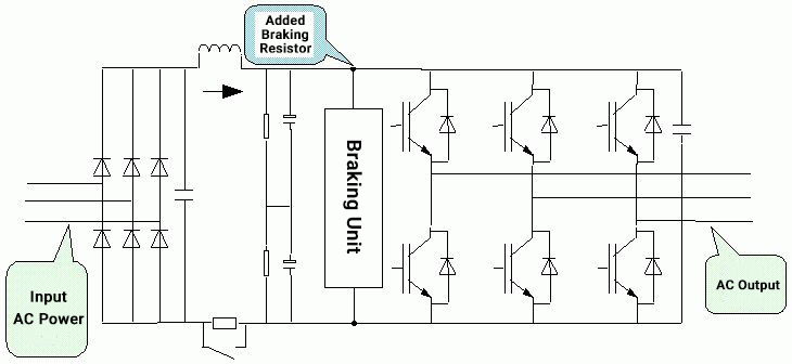
By adding a braking resistor and a braking unit to both ends of the DC bus in the main circuit of the VFD (this method has a high cost-effectiveness ratio), due to the need for high torque during the startup and ascending phase of the sucker rod pump, and during the descending phase, the motor is in a power generation state. The most critical part is the descending phase, which is a continuous operation process, while adjusting the reciprocating motion per minute according to the oil viscosity, well depth, and production rate, causing the motor to enter a regenerative power generation state, feeding excess energy back to the grid, leading to an increase in the voltage on the DC bus of the main circuit of the VFD. Without a path for electrical energy to flow back to the grid, it must be dissipated locally using resistors. This is why we must use a braking unit and braking resistor on the VFD, and our company's high-power VFDs can have built-in braking units, fully achieving the desired control effect.
2.VFD with Regenerative Feedback Unit Control
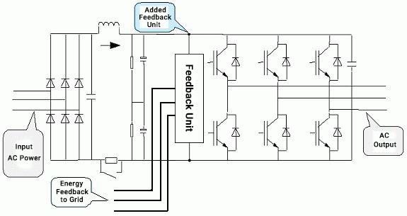
A regenerative feedback unit is added to the DC circuit of the VFD to feed the electrical energy generated during the motor’s regenerative (power generation) state back into the grid.
3.VFD Automatic Intelligent Control — No Braking Unit or Regenerative Feedback Unit Required
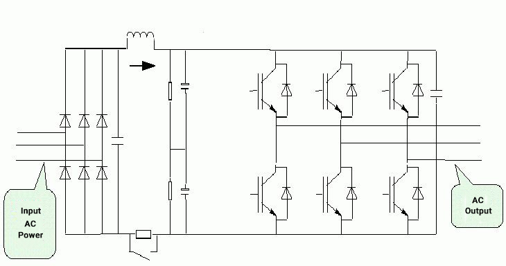
In general, no braking unit or regenerative feedback unit is required. The VFD can automatically adjust its operation according to the working conditions of the beam pumping unit, resulting in lower system cost, higher reliability, reduced harmonic pollution, and better adaptability to operating voltage variations.
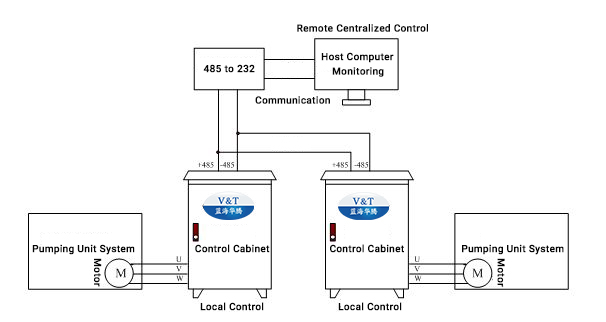
Two-Location Control for the Variable Frequency Speed Control System
As per requirements, each variable frequency speed control cabinet is equipped with one VFD, which automatically controls the motor in open-loop speed mode. The control cabinet features a switch between line-frequency (bypass) and variable-frequency operation, offering three positions: line-frequency, variable-frequency, and stop—ensuring simple and convenient operation.
When switched to variable-frequency mode, the VFD runs automatically. Speed adjustment is achieved by feeding an analog signal from the potentiometer on the control cabinet to the AI1 terminal of the VFD. During operation, real-time parameters such as current, voltage, power, and frequency can be viewed directly on the VFD’s display panel.
For upper-level (remote) control, no switching is required—the VFD can be started and stopped directly, and its operating status and running frequency can be set remotely. Current operational data can also be copied and exported into documentation.
Product Advantages:
 3-8th Floor, Tower 2, Zhiyan lnnovation Building, Yutang Street, Tianliao Community, Guangming District, Shenzhen, Guangdong Province, China.
 Ms. Nina


If you are interested in our products and want to know more details,please leave a message here,we will reply you as soon as we can.


